CANny Datasheet
Introduction
The CAN FD card (CANny) is considered to be used as standalone card for CAN FD communication. The card consists of three CAN FD controller with each two CAN FD interfaces (6 fold). The card can be accessed via Ethernet. Each of the controller has its own IP address.
Additionally 12 LIN interfaces are provided on the card (software to address the LIN interfaces is not implemented yet).
Purpose of this document
Purpose of this document is to describe how to integrate the module in a test system and how to access it from the software point of view. Limits of application are shown in the technical data section.
This document is addressed to system integrators and the users, who are applying the module.
Hardware
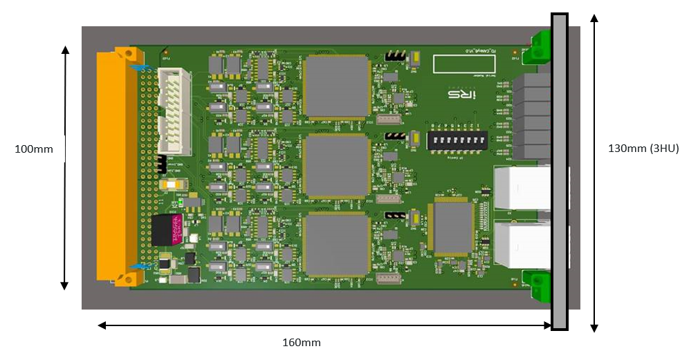
Dimensions
CANny Card is designed on a 160mmx 100mm Euro card, including front cover with a width of 25,4mm (5HP) and a standard DIN41612 connector. With this dimensions it fits to standard 19” / 3HU carriers and racks.
Pinning VG connector at CANny Card
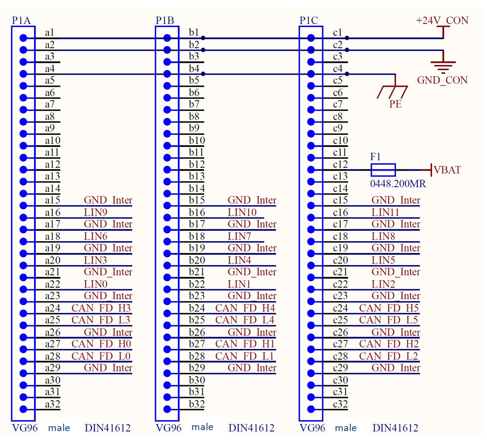
Notes
GND Inter Pins are related to the corresponding communication PIN and have to be connected to the appropriate DUT GND.
Pin c12 (VBAT) is used for the LIN level and should be connected to V Battery (or Kl30) of the DUT.
Technical Data
Power supply
| Item | Min | Typical | Max | Unit |
|---|---|---|---|---|
| Supply voltage range | 22 | 24 | 26 | V |
| current consumption | 400 | 400 | mA |
Access to the CANny Card
The card can be accessed via ethernet port. The last numbers of the start IP address can be selected via dip switch. The main IP Address is: 192.168.222.xxx . There is a .dll library available to configure the CANny card and to send CAN FD messages. The IP address is represented by 8 bits. However bits 0,1 and 7 are reserved for internal usage. The remaining 5 bits can be set via the DIP switches 1 to 5. Keep in mind the significance of each bit! (E.g. Dip 2 On = 8 = 2^3)
| Bit 0 | Bit 1 | Bit 2 | Bit 3 | Bit 4 | Bit 5 | Bit 6 | Bit 7 |
|---|---|---|---|---|---|---|---|
| x | x | Dip 1 | Dip 2 | Dip 3 | Dip 4 | Dip 5 | x |
Setup the IP Address
Example how to set the IP address:
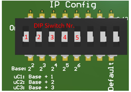
The address is calculated in the following way: Important: Base IP Address for Signalconfig.xml No Dip Switch = 0 Dip Switch Nr. 1 -> 2^2 = 4 Dip Switch Nr. 2 -> 2^3 = 8 Etc.
Controller IP Address -> Base IP Address (0) +1/+2/+3
IP Address of Controller 1 (CAN FD ch0 and ch1): 192.168.222.1
IP Address of Controller 2 (CAN FD ch2 and ch3): 192.168.222.2
IP Address of Controller 3 (CAN FD ch4 and ch5): 192.168.222.3
Another Example: Base IP Address: Dip Switch Nr. 1 + Dip Switch Nr. 2 -> 2^2 + 2^3 = 12
IP Address of Controller 1 (CAN FD ch0 and ch1): 192.168.222.13 IP Address of Controller 2 (CAN FD ch2 and ch3): 192.168.222.14 IP Address of Controller 3 (CAN FD ch4 and ch5): 192.168.222.15
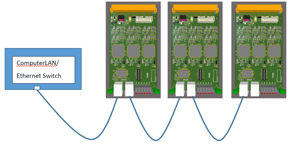
Connection of more CANny Cards
Each CANny card has an implemented Ethernet switch. So you can easily wire from one card to another.