Loading...
Loading...
Loading...
Loading...
Loading...
Loading...
Loading...
Loading...
Added: Support for CMM-3CH variant
Changed: Updated GCC compiler version
Changed: Default values are now active directly after the command was used. No need for a reset.
Fixed: Bug which sets wrong data baudrate when IsoTP is used to set baudrates
Fixed: Bug which can result in all gates switched off, when CMM is switched on
Added: Command "ReadCurrent"
Added: Commands "SetTime" and "GetTime"
Added: Timestamp in command "ReadCurrent"
Added: IsoTp command "GetSerialNumber"
Changed: Rename project to IRS-CMM-xCH-FW
Added: FIFO for IsoTP RX messages
Fixed: Bug which rejected padded IsoTP messages
Added: Legacy mode for cyclic message
Added: Command LegacyConfig to make ID for legacy mode configurable
Added: FDCAN command RestoreDefault
Changed: Rename command IsoTpConfig to LegacyConfig
Fixed: Bug in SaveConfiguration()
Fixed: Added missing flag in "send cyclic message"
Fixed: Bug in deserialization functions
First public release
You can download the latest GUI on the download page.
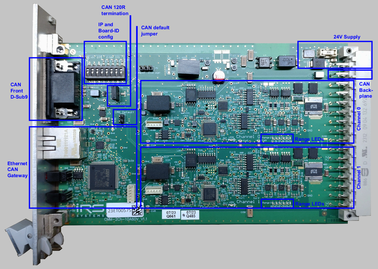
At delivery the IP address of the module is set to 192.168.222.1. You can configure the IP address in a limited range with the DIP switch on the PCB. The switches are treated as a binary number and marked with their place value (1, 2, 4). Depending on the set binary number an IP address between 192.168.222.1 and 192.168.222.7 is used. If all three switches are "off" the default IP address is used.
You can change the default IP address of the module with "Tools -> DiscoveryTool" in the IRS-CMM-xCH GUI. See CMM-xCH-GUI-Manual for details.
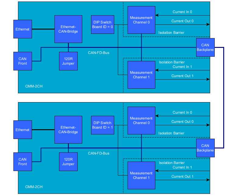
The Ethernet-CAN-Gateway and the two Channels are connected via CAN-FD. At delivery the CAN-FD is configured to 1000 kBit/s without bit rate switching. If necessary, the baudrate settings can be changed in the IRS-CMM-xCH-GUI. The settings can be reset to their default values with the "CAN default jumper". See CMM-xCH-GUI-Manual for more details. A single termination resistor is installed on the board and is activated with the "CAN 120R jumper". This single termination resistor is sufficient for one single CMM-2CH without bit rate switching. If you want to connect multiple CMM-2CH or use bit rate switching a proper external termination of the CAN bus with two resistors at both ends of the CAN harness is highly recommended. Without proper termination a reliable communication between the Gateway and the Channels may not be possible.
Multiple CMM-xCH boards can be connected via CAN bus. To address the individual boards, each board needs to be configured with a unique Board ID.The configuration of the Board ID is done with the DIP switch on the board marked with "CAN ID". The switches are treated as a binary number and marked with their place value (1, 2, 4, ...). The switches are read at power up. So after changing the Board ID a power cycle is required.
In the GUI switch to the tab "Measurement" and either use the Button "MIN/AVG/MAX" or enable cyclic messages. For details see CMM-xCH-GUI-Manual.
If the CMM-2CH is connected to a MesSy-II or MesSy-II-FD you can use the integrated Messy CMM API to read min, max and average values. For details see MesSy documentation.
You can either query min, max and average values with a CAN message or enable cyclic messages. You can use the the IsoTP protocol which is known from CMM III and CMM IV or a new protocol which is based on CAN-FD. For the details of the new protocol we can send you a DBC or SYM file on request.
Version: 1.1 | Author: madi1 | Last Update: 13.12.2024 | Revison History
The CMMs are designed as sensitive measurement devices which can measure currents as low as 1µA. Therefore they offer little protection against voltage spikes and have no integrated freewheeling diode or other protective circuitry, because this circuitry would add unwanted measurement errors.
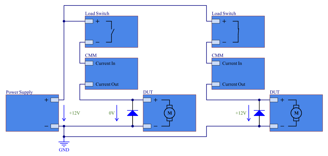
If you need to switch DUTs on and off, you should use a suitable load switch like a relay. A recommendation for two DUTs which are powered from the same power supply is illustrated in the image below. IRS can help you to find a suitable solution for your application and offers a load switch which can be directly connected to the CMM-3CH. Please contact IRS for further information.
If you really need to use the CMM as a switch there are at least two possible problems which should be considered:
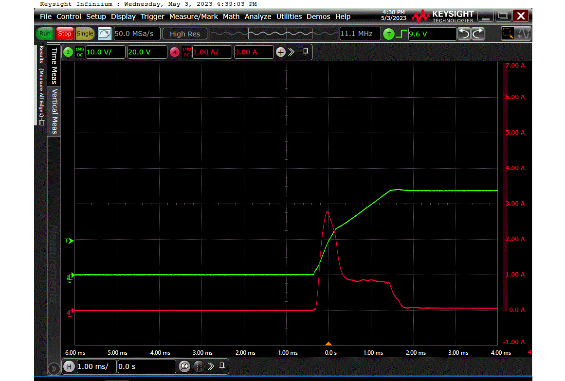
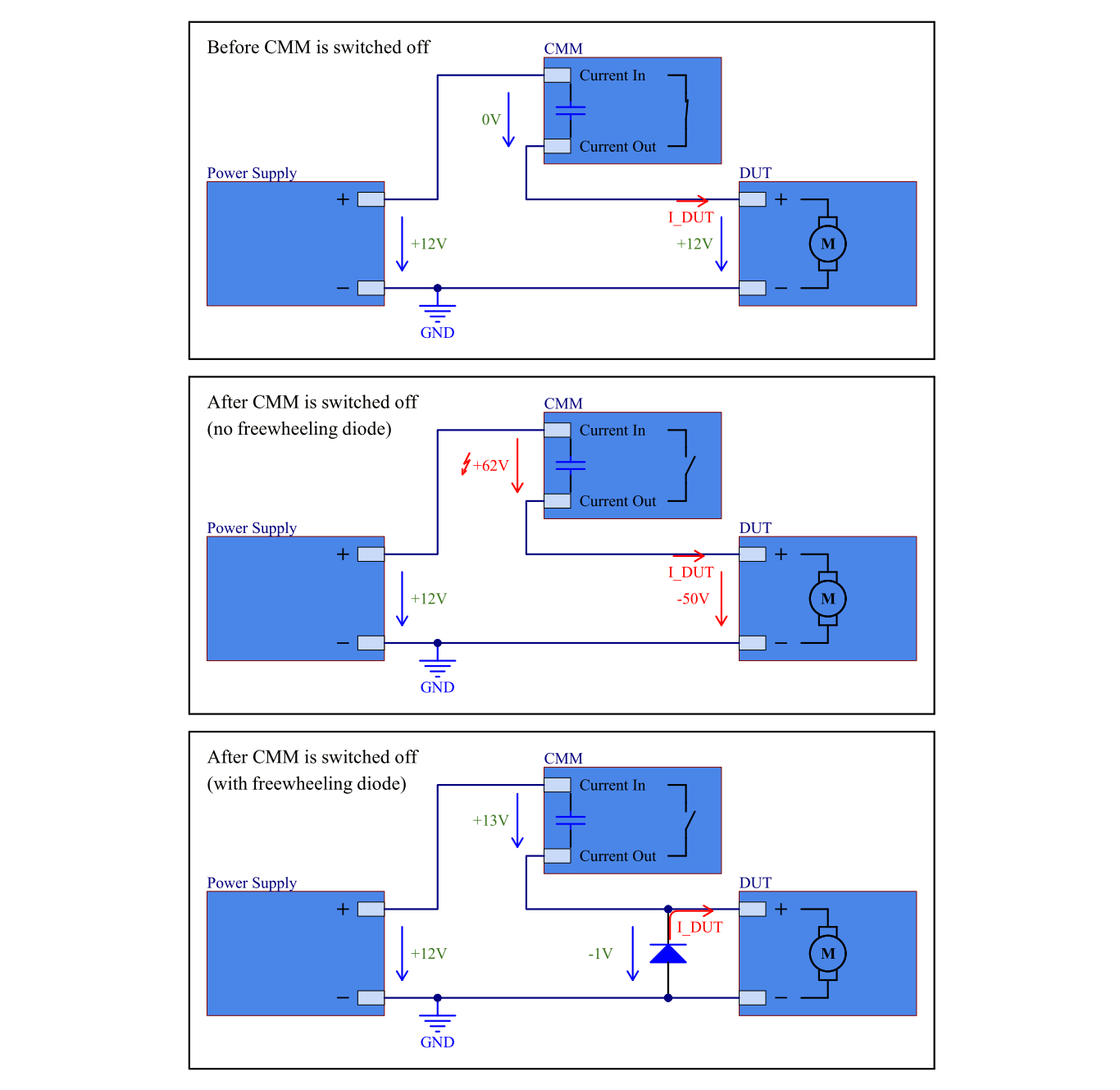
If an inductive load is switched off, the energy stored in the load is released. This energy can cause a voltage spike which can exceed the maximum voltage rating of the CMM. The following image illustrates the problem:
If you need to switch the CMM while an inductive load is connected, you must always connect a freewheeling diode to the load to protect the CMM. Our recommendation is NOT to use the CMM as a load switch. Use a suitable load switch instead.
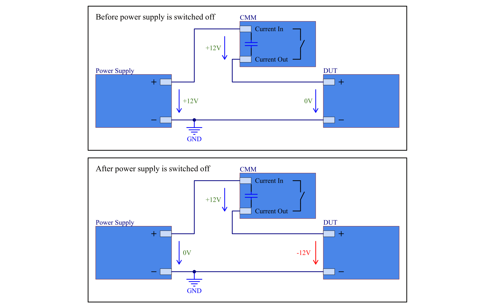
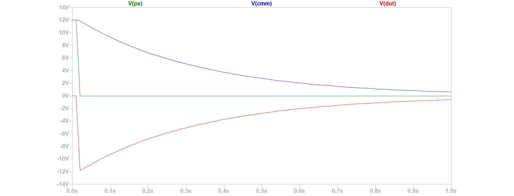
The CMMs have a built-in capacitor to smoothen current measurements. If a CMM is open, either because it is not powered or because it is switched to the "open" state, the capacitor is charged to the supply voltage. If the supply voltage is then switched off, while the CMM is still open, the capacitor remains charged and a negative voltage is seen by the DUT.
The following images illustrate the problem:
This problem mainly occurs with DUTs which have a high input impedance (for example a DUT in sleep mode) and therefore cannot discharge the capacitor quickly. The negative voltage could either damage the DUT or a connected measurement device like the MesSy-II.
madi1
Clarify recommended termination of CAN bus
1.0
07.11.2023
madi1
Initial Release
1.1
13.12.2024
madi1
Add info about load switches from IRS
1.0
07.11.2023
madi1
Initial Release
1.1
13.12.2024
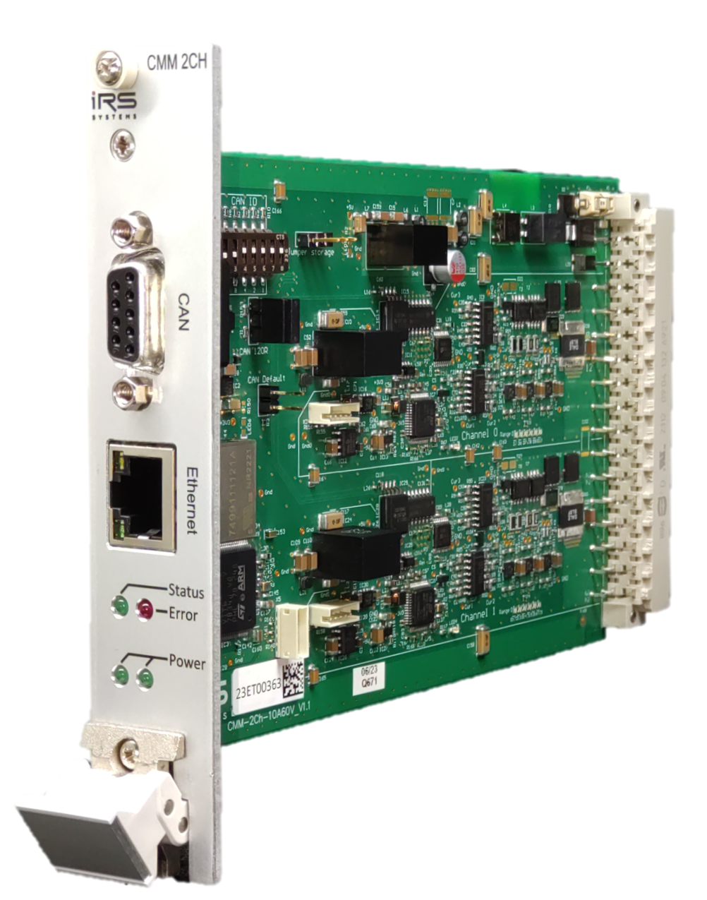
The CMM-xCH modules are equipped with an Ethernet-CAN-Gateway and independent microcontrollers for each measurement channel. CAN-FD is used to communicate between the gateway and the channels.
The CMM-xCH modules can be connected via Ethernet or with a direct connection to the internal CAN Bus.
For CAN-FD communication a DBC file is available on request. For communication via Ethernet the tool "IRS.CMM-xCH" can be used. It can be downloaded from https://docs.irs.systems/. Alternatively the "IRS.CMM-xCH.Shared.dll" can be used to integrate the CMM-xCH modules into your Software.
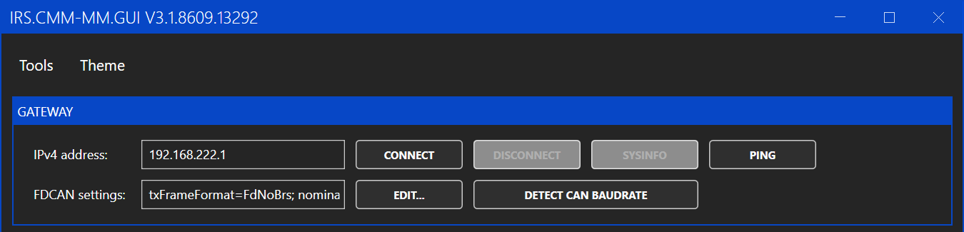
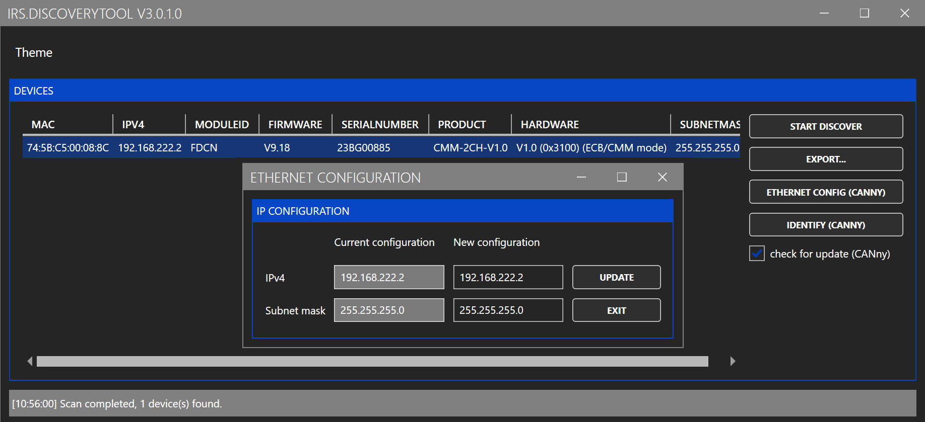
To connect to the module, enter the IP address of the module and click connect. If you do not know the IP address of the module you can use "Tools -> DiscoveryTool" to detect connected modules.
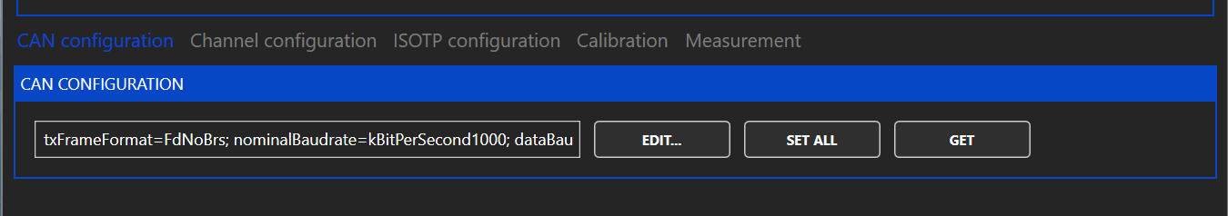
The FDCAN settings are used for the internal communication and normally the default setting can be used. If the settings were changed before, the "EDIT" button can be used to select the changed settings. If the settings are unknown the "DETECT CAN BAUDRATE" button can be used.
To change the IP address of the module, use "Tools -> DiscoveryTool". In the DicoveryTool first click "START DISCOVER". After 10 seconds a list of all connected modules is shown. Select the module you want to change and click "ETHERNET CONFIG". In the following window you can enter the new IP address and click "UPDATE". You need to power cycle the module to apply the new IP address.
As an alternative you can configure the IP address in a limited range with the DIP switch on the PCB. The switches are treated as a binary number and marked with their place value (1, 2, 4). Depending on the set binary number an IP address between 192.168.222.1 and 192.168.222.7 is used. If all three switches are "off" the IP address configured with the DiscoveryTool is used. The switches are read at power up. So after changing the switches a power cycle is required.
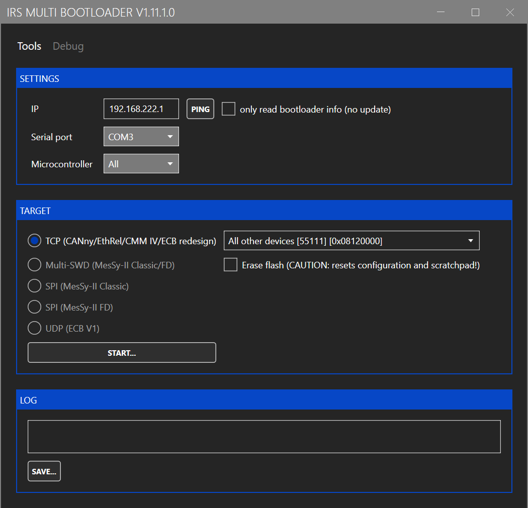
To update the Ethernet-CAN-Gateway firmware, use "Tools -> Bootloader Gateway". This opens the following window:
Enter the IP address and click on "START". Select the firmware image in the file selection dialog. The firmware image is include in the folder "firmware" of the GUI installation folder and named "STM32H7-Gateway.tinyimg2".
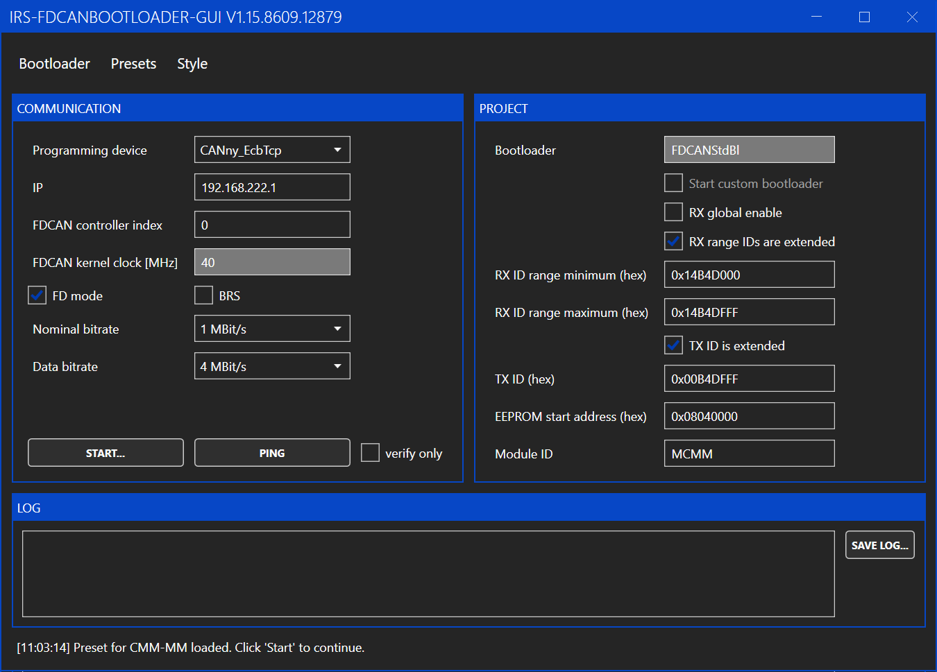
To update the firmware of the measurement channels, use "Tools -> Bootloader CMM". This opens the following window:
You only need to enter the IP address of the module and then click "START". The rest of the settings should be preset to the correct values. If the settings were changed, you can reload the default values by clicking "Presets -> CMM-xCH".
After clicking on "START", select the firmware image in the file selection dialog. The firmware image is include in the folder "firmware" of the GUI installation folder and named "STM32G4-Channel.tinyimg1".
Multiple CMM-xCH boards can be connected via CAN bus. To address the individual boards, each board needs to be configured with a unique Board ID.
The configuration of the Board ID is done with the DIP switch on the board marked with "CAN ID". The switches are treated as a binary number and marked with their place value (1, 2, 4, ...). The switches are read at power up. So after changing the Board ID a power cycle is required.
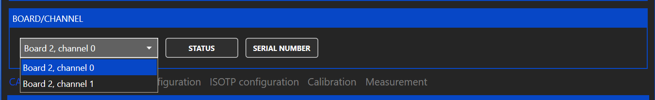
When the Board IDs are set correctly, you can use the Ethernet-CAN-Gateway of any board to communicate with all connected boards. In the GUI click the dropdown menu under "BOARD/CHANNEL to see a list of all detected channels and to select the channel which shall be used. The channel IDs are fixed to 0 and 1 and can not be changed. The channels are marked on the PCB with "Channel 0" and "Channel 1".
CAN baudrates and the uses of bitrate switching can be configured under "CAN CONFIGURATION".
CAN configuration can only be set for all connected channels not for individual channels. Otherwise communication between the channels could get broken, if different baudrates are set.
If the CAN configuration of connected boards is messed up and a configuration with the GUI is not possible you can use the jumper marked with "CAN Default" to reset the CAN configuration of the boards. The CMM-2CH needs to be power-cycled while the jumper is connected to reset the CAN configuration to its default value.
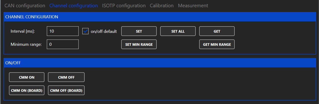
The channels of the CMM-xCH can send a cyclic CAN message with the measured values. Under "CHANNEL CONFIGURATION" the interval of these cyclic CAN messages can be adjusted. If the interval is set to zero, no cyclic CAN message are sent.
Furthermore the default state after power up of each measurement channel can be configured. If the default state is "off" the button "CMM ON" can be used to switch the measurement channel on.
The CMM-xCH modules automatically switch between ranges without interrupting then current flow in the measurement path. If however this switching is not desired, a minimum range can be set. The minimum range is reset to zero when rebooting the CMM-xCH.
A maximum range can not be set because it could easily lead to accidentally exceeding the maximum allowed current of the selected range.
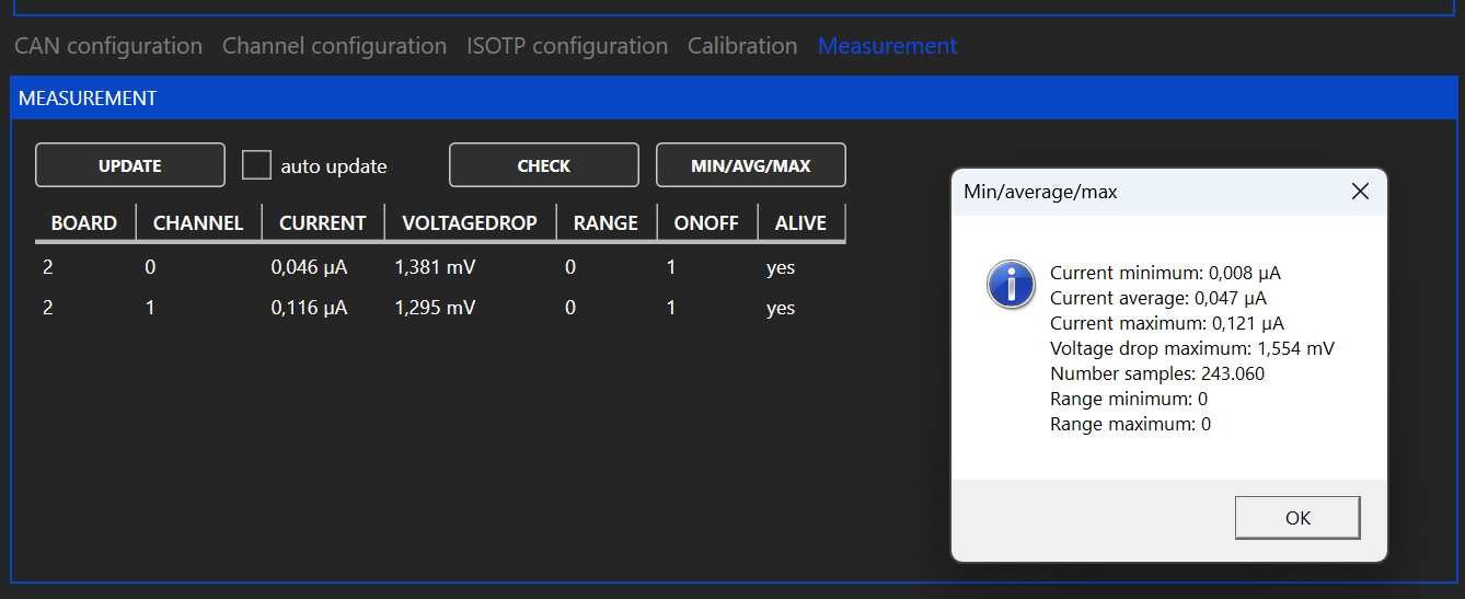
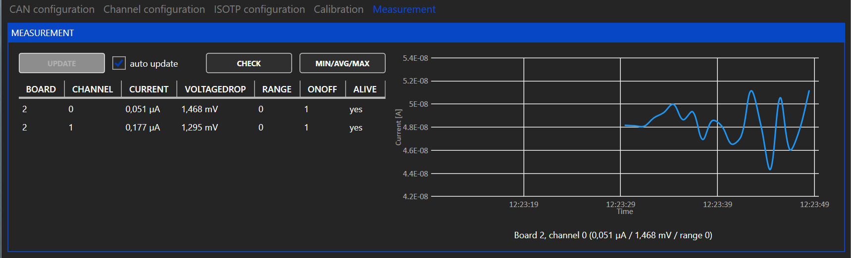
To read the measured values, the button "MIN/AVG/MAX" und "MEASUREMENT" can be used. A pop up window opens, which shows the measured values since the last use of the button.
For continuous monitoring of the measured values the cyclic messages can be used. To use the cyclic messages a interval different from zero must be set under "CHANNEL CONFIGURATION". The cyclic message can be read by clicking the button "UPDATE" or by enabling the checkbox "auto update".
If auto update is enabled the chart on the right shows the current of the channel selected under "BOARD/CHANNEL".
The CMM-xCH supports a legacy IsoTP communication mode to be compatible with software using the IsoTP communication of CMM-III. The IDs for the IsoTP interface can be configured in the GUI. For further information please contact IRS.
1.0
07.11.2023
madi1
Initial Release
1.1
13.12.2024
madi1
Refactor tool names and add document info
CMM-2CH and CMM-3CH can be controlled via CAN-FD. Each measurement channel has its own microcontroller. The nominal baudrate is 1 MBit/s, the data baudrate is 4 MBit/s. A DBC file is available on the download page.
The CAN IDs are build with the following scheme.
The highest value of board (0xFF) and channel (0xF) is used as broadcast. For example the ID 0x 0 00 4D 01 F is the command "SetOnOff" (= 0x01) for all channels on board 1.
Physical values are always transmitted as float (32 Bit / Single Precision / LSB first) and in the base unit (V / A / sec / °C / ... ).
Get-ID and Response-ID are the same, because the already differ in the direction bit 28. The command values in the following table include the direction bit, to make this clear.
Physical values are always transmitted as float (32 Bit / Single Precision / LSB first) and in the base unit (V / A / sec / °C / ... ).
StatusCode (U8), Command (U8)
0x001
0x041
0x141
OnOff
1
OnOff [0/1] (U1)
0x002
-
-
OnOffSelected
1
EnableMask_Board (U8)
0x003
0x043
0x143
MinRange
1
MinRange (U8)
0x004
0x044
0x144
MinMaxAvg
24
CurrentMin [A] (float), CurrentAvg [A] (float), CurrentMax [A] (float),
VoltageDropMax [V] (float), NoOfSamples (U32), RangeMin (U8), RangeMax (U8)
0x005
0x045
0x145
ChannelConfig
5
OnOffDefaultValue [0/1] (U1), MeasuredValuesInterval [sec] (float)
0x006
0x046
0x146
CanConfig
3
TxFrameFormat [Enum] (U8), NominalBaudrate [Enum] (U8), DataBaudrate [Enum] (U8)
0x007
0x047
0x147
LegacyConfig
16
LocalId (U32), LocalIdIsExt (U1),RemoteId (U32), RemoteIdIsExt (U1)
LegacyCyclicId (U32), LegacyCyclicIdIsExt (U1), LegacyCyclicMessageEnable (U1)
-
0x048
0x148
Version
12
HardwareType (U8), FirmwareVersion (U16), CompileTimestamp (U32),
WarningRegister (U16), HardwareVersion (U8)
-
0x049
0x149
SerialNumber
12
SerialNumber (String 12 Bytes)
0x00A
-
-
RestoreDefault
0
-
0x00D
0x04D
0x14D
DisableCalibration
1
DisableCalibration [0/1] (U1)
0xE2
Parameter out of range
0xE3
Flash error
0xE4
Flash verify error
0xE5
Command not allowed
0xE6
Firmware hardware mismatch
0xE7
File not found
WARNING_INVALIDCALIBRATION
0x0008
WARNING_DISABLEDCALIBRATION
0x0010
WARNING_ISOTPRXFIFOFULL
0x0020
48
ErrorType (U8), FileNumber (U8), LineNumber (U16), more info
28
0x10000000
Direction
0: PC to uC, 1: uC to PC
27-20
0x0FF00000
Command-ID
0...255 see section Commands
19-12
0x000FF000
Module-ID
"M" = 0x4D
11-4
0x00000FF0
Board-ID
0...31 (Can be set via DIP switch on CMM-2CH), 255 = 0xFF = broadcast to all boards
3-0
0x0000000F
Channel-ID
0...2 (Is hardwired on CMM-xCH), 15 = 0xF = broadcast to all channels
-
-
0x140
CommandResponse
0xA0
Success
0xE0
Unknown command
0xE1
Invalid DLC
WARNING_CANRXFIFOFULL
0x0001
WARNING_CANTXFIFOFULL
0x0002
WARNING_CANBUSOFF
0x0004
0x180
MeasuredValues
12
Current [A] (float), Range (U8), VoltageDrop [V] (float), OnOff [0/1] (U1)
0x18E
2
ErrorHandler

CMM-3CH-5A60V
This module offers two separately isolated channels for current measurements over a wide range from 1µA to 5A. Ethernet and CAN-FD are available for communication. Current is measured in six automatically selected ranges as listed in the table below:
Connect the power supply between +24V-CON and GND-CON. It is strongly recommended not to use the DUT power supply to power the CMM. Please note that the current path is interrupted when the module is unpowered.
The module’s accuracy is verified for DC currents during in-house calibration. The module may of course be re-calibrated. See for more info.
The following table lists the voltage across the module’s current input and output pins for specific current values. These are typical values, measured at room temperature at the connector pins of one channel.
The module supports 10Mbit/s and 100Mbit/s Ethernet on the RJ45 front connector. Default IP: 192.168.222.1
The module provides a CAN-FD interface on the front via a 9-pin D-Sub connector as well as on the backplane connector.
120Ω on-board termination is available via jumper. On-board termination is only recommended if a single module is used without further devices connected via CAN. If multiple devices are connected via CAN, it is recommended to use external termination on both ends of the CAN harness. This avoids problems when modules are swapped or replaced.
Connector type: Harting 09041326921 Please make sure you use all connector pins for current in / current out. A backplane-pcb is available for easy connection with just two pins per current measurement channel.
IRS recommends a recalibration within 2 years.
The calibration should be performed for each channel at multiple calibration points for all 6 ranges. IRS recommends measuring at least the following currents.
Current values should be captured with the function (IRS.CMM-xCH.Shared.Gateway).GetMinMaxAverage. This function returns the value averaged since last read.
Before capturing a valid value, enable the calibration current, perform a dummy read and wait 100 ms.
The fluctuations of the power source used should not exceed 0.1% of the nominal value.
Worst case DC current
8
A
25° Ambient Temperature with airflow >2m/s
Maximum measurable current
15
A
Single pulse current
25
A
max. 100ms
DC Current per pin on backplane connector
6
A
Voltage across current in/out when module is off
60
V
Leakage current @ OFF
100
µA
60V across module , temperature 25°C
Isolation rating
-150
150
V
Maximum allowed voltage difference between module supply and current path
Reverse current continuous
3
A
Reverse current single pulse
25
A
Max. 100ms
+24V-CON to GND-CON
Supply current (Ethernet port active)
110
mA
Supply voltage = 24V
Supply current (Ethernet port inactive)
95
mA
Supply voltage = 24V
Supply inrush current
3
A
Inrush current for < 1ms @ dU/dt ≈ 20V/ms, 24V supply
Accuracy calibrated
0,2
1
%
% of respective range’s maximum current
Resolution range 0
40,4
nA
Resolution range 1
404
nA
Resolution range 2
4,04
µA
Resolution range 3
40,3
µA
Resolution range 4
403
µA
Resolution range 5
4,03
mA
mV
Range 1
Drop @ 10mA
55
mV
Range 2
Drop @ 100mA
60
mV
Range 3
Drop @ 1A
60
mV
Range 4
Drop @ 10A
110
mV
Range 5
Drop @ 15A
170
mV
Range 5
C4
CAN High
A6
Channel 0 Current In
C6
Channel 0 Current In
A8
C8
A10
C10
A12
Channel 0 Current Out
C12
Channel 0 Current Out
A14
Channel 1 Current In
C14
Channel 1 Current In
A16
Channel 1 Current Out
C16
Channel 1 Current Out
A18
C18
A20
C20
A22
C22
A24
Channel 2 Current In
C24
Channel 2 Current In
A26
Channel 2 Current Out
C26
Channel 2 Current Out
A28
C28
A30
C30
A32
C32
100 mA
10 mA, 20mA, 40 mA, 60 mA, 80 mA, 100 mA
1 A
0.1 A, 0.2A, 0.4 A, 0.6 A, 0.8 A, 1 A
10 A
1 A, 3 A, 5 A, 8 A, 12 A, 15A
miho1
Updated current values, connector pinning
0
1µA
100µA
-
110µA
1
100µA
1mA
90µA
1.1mA
2
1mA
10mA
0.9mA
11mA
3
10mA
100mA
9mA
110mA
4
100mA
1A
90mA
1.1A
5
1A
15A
900mA
Module dimensions
160mm x 100mm (Eurocard)
19” specification
5 TE x 3 HE
Ambient operating temperature
5…50°C
Storage temperature
-20…70°C
Humidity
5…80% noncondensing
DC current
5
Supply voltage
20
24
26
Accuracy uncalibrated
0,5
2
%
% of respective range’s maximum current
Drop @ 100µA
50
mV
Range 0
Drop @ 1mA
Supported nominal bit rates
500 kbit/s, 1 Mbit/s
Supported data bit rates
1 Mbit/s, 2 Mbit/s, 4 Mbit/s
Default settings
1 Mbit/s nominal, 4 Mbit/s data, no bit rate switch
A2
+24V module supply
C2
0V module supply
A4
100 uA
1uA, 20 uA, 40 uA, 60 uA, 80 uA, 100 uA
1 mA
0.1 mA, 0.2mA, 0.4 mA, 0.6 mA, 0.8 mA, 1 mA
10 mA
1 mA, 2mA, 4 mA, 6 mA, 8 mA, 10 mA
1.0
28.07.2025
madi1
Initial Release (copied from CMM-2CH)
1.1
A
V
50
CAN Low
28.07.2025